
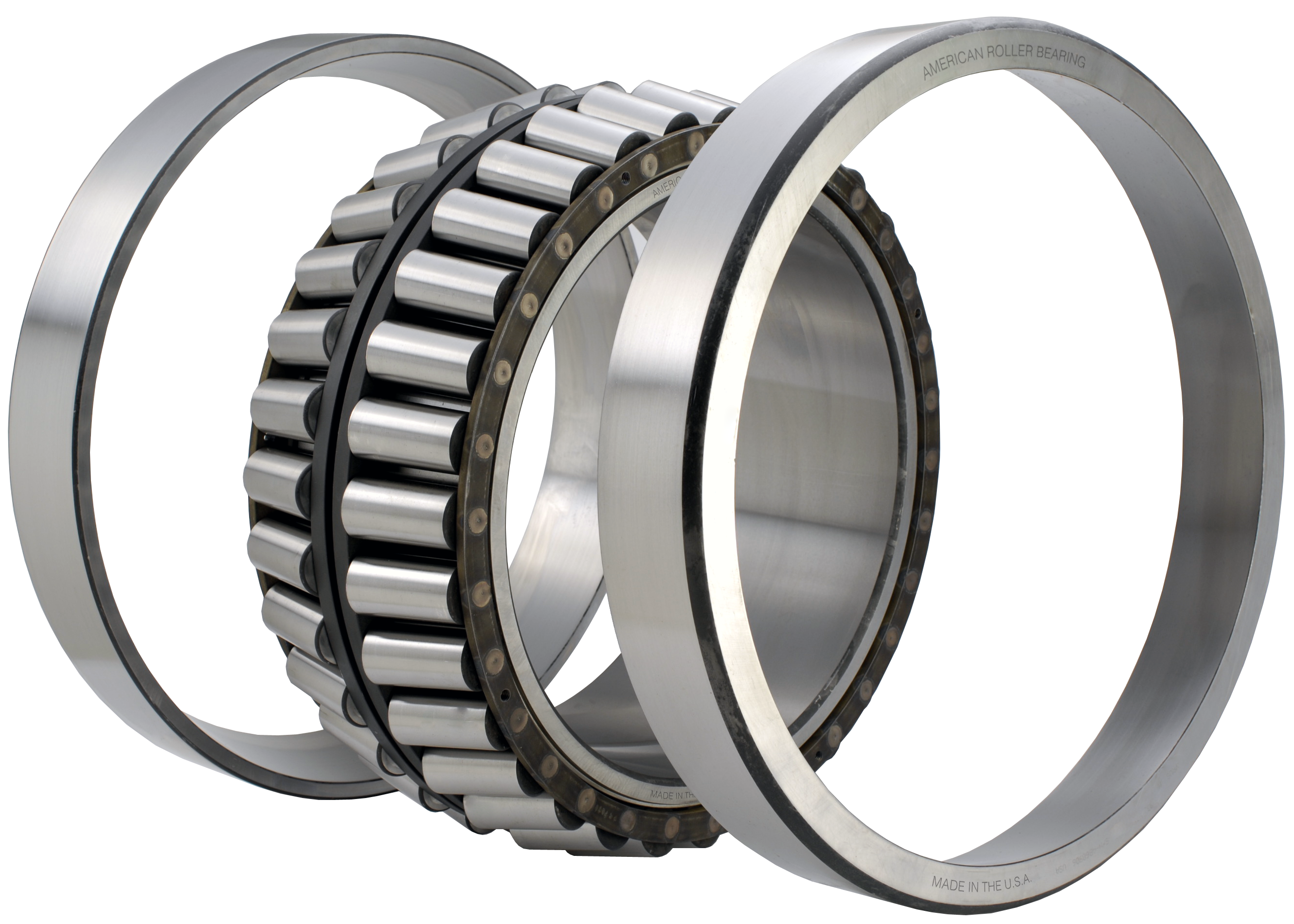
American Roller Bearings
Edited by Mike Santora
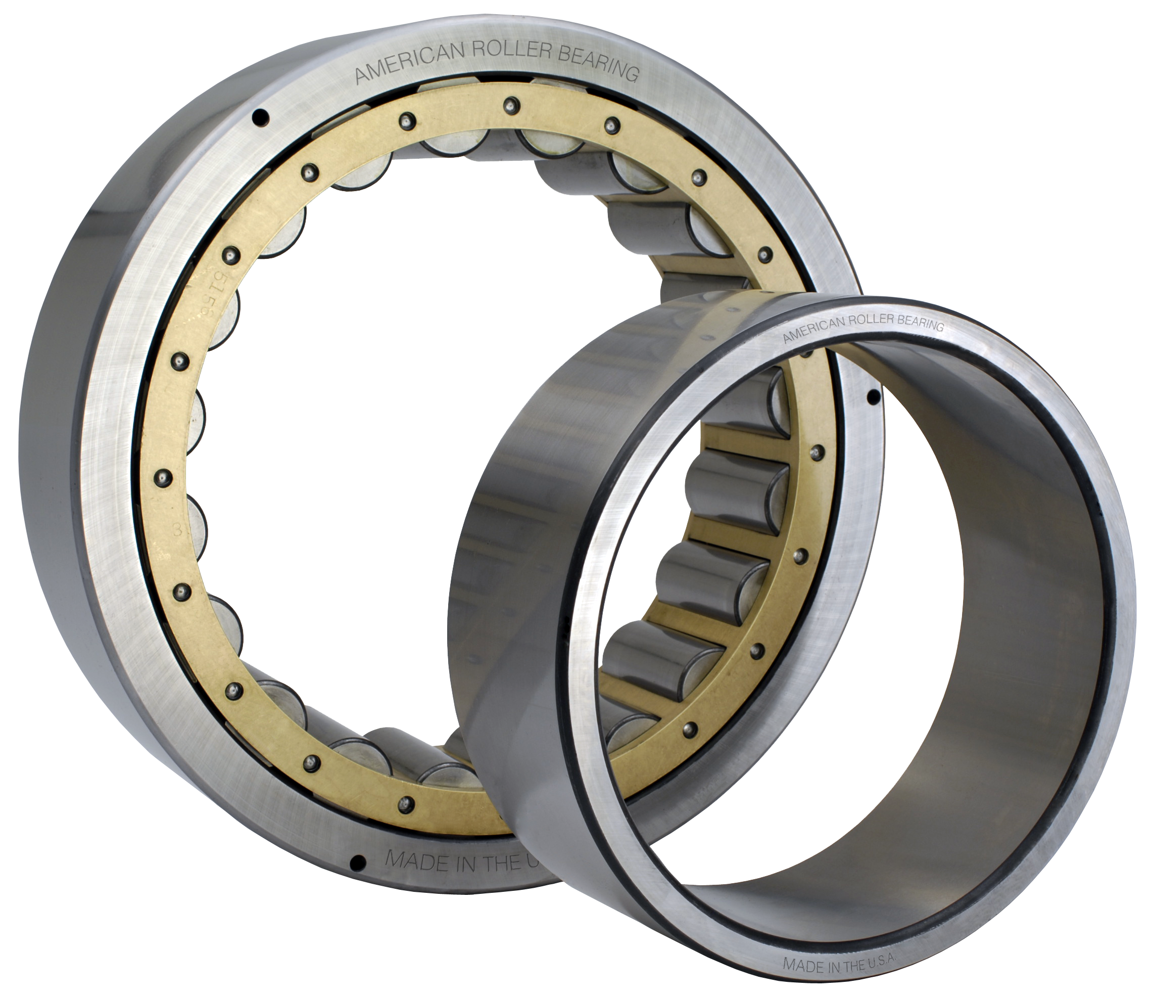
Rolling element bearings, such as ball bearings and roller bearings, are used in equipment primarily because they support the loads inherent to the machine’s function at a much lower friction level than oil film bearings such as bronze or Babbitt. This reduces the power required to drive the equipment, lowering the initial cost of the prime mover and the energy to operate it.
While sometimes generically referred to as “Anti-Friction” bearings, there is a small amount of friction or resistance to rotation in every ball and roller bearing. The sources of this friction are: slight deformation of the rolling elements and raceways under load, sliding friction of the rolling elements against the cage and guiding surfaces. Different bearing types, because of their internal designs, result in slightly different amounts of internal friction.
Lubrication
A contributor to bearing internal friction is the lubricant, grease or oil that is continually pushed aside as the rolling elements circulate around the raceways. A proper lubricant will reduce friction between the internal sliding surfaces of the bearings components and reduce or prevent metal-to-metal contact of the rolling elements with their raceways. Proper lubrication reduces wear and prevents corrosion, insuring long service lives for bearings.
Lubrication, especially circulating oil, will also remove heat from the bearing. There are two basic types of bearing lubricants readily available: Oil and Grease. The former is fairly simple to understand being a free-flowing liquid, while the latter is a little more complex. To be a lubricant, all greases have oil that is entrained in a thickened base. This base gives the impression that grease is a more viscous type of oil; however, it is the oil in the grease that does the actual lubricating. Each type of lubricant has its own advantages and disadvantages and is selected based on the nature of the application.
Each manufacturer of a lubricant can supply a specification sheet for each of their products, and each sheet will have a list of about 20 properties and values related to the lubricant. The most important property of any lubricant for rolling element bearings is oil viscosity. If the specification sheet is for an oil, the viscosity values will be for the oil. If it’s a grease, it should refer to “Base Oil Viscosity” or another similar term, depending on the manufacturer. Usually, four viscosity values are shown as follows:
cSt @ 40° C(104°F) SI units
cSt @ 100°C (212°F) SI units
SUS @ 100°F(38°C) Imperial units
SUS @ 210°F(99°C) Imperial units
It is important to select a lubricant that will provide a minimum acceptable viscosity at the bearing’s operating temperature, which will usually be between the lowest and highest reference temperatures shown above. Typically, oil viscosity numbers decrease rapidly with increasing temperature. Often, previous experience with an existing similar machine will indicate an acceptable lubricant. In house testing of a prototype or the first machine can indicate operating temperatures. Most machines use a lubricant that is selected to match the most severe demand of one component in the machine such as a bearing, gear, and so on.
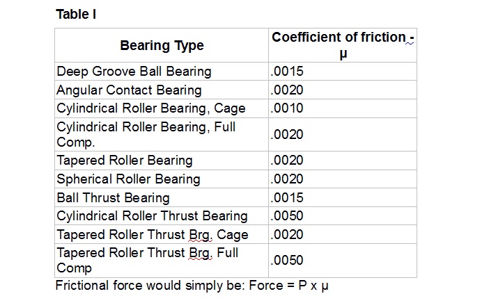
Coefficients of friction for the various types of bearings are based on a reference value of lubricant viscosity of 20 cSt/100SUS at the bearing’s operating temperature. Coefficients of friction for different bearing types are shown in Table I.
If a more accurate calculation of bearing friction taking into account the effects of speed and lubrication is required for an application, the manufacturer should be contacted. More important to the equipment designer than frictional force is the amount of frictional torque that must be overcome. This parameter can easily be calculated using the formula below:
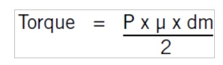
where:
P = Equivalent Load on the bearing
μ = Coefficient of friction
dm = Pitch diameter of bearing
Lastly, the amount of power consumed by bearing friction can be easily calculated using the appropriate SI or Imperial formula knowing the resistance Torque and RPM.
Vibration frequency factors
More and more manufacturers and end users use vibrational analysis to monitor the operation of their equipment to detect the onset of component failure. The primary suspects are bearings and gears, two components that are subjected to the highest stresses in operation. However, other machine components subjected to cyclic stresses can also deteriorate and eventually fail. There is often a window of opportunity between deterioration and complete failure when the machine component will announce its condition by an increased level of vibration or noise. An increase in vibration level can affect the quality of the product produced, but the greatest value of vibrational monitoring is the early warning of an impending failure. This allows plant operators to schedule a convenient shutdown time and maintenance workers to efficiently plan the removal and replacement procedure. Another advantage of having foreknowledge of impending component failure is to be able to remove the component before total failure thus preventing pieces of the failed component from getting into and damaging other components.
A bearing, like a gear or other machine component, can predictably generate an impulse whose frequency is directly related to the input RPM of the machine. When the spectrum of a vibration monitoring indicates a higher than normal amplitude at a certain frequency, the analysis proceeds to match this frequency with the machine component that could produce this frequency, thus identifying the cause and eliminating other components from consideration.
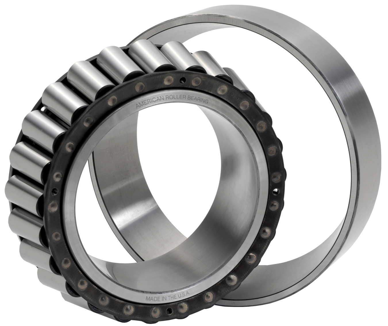
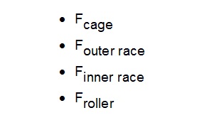
Each typical bearing has four major components, and if damaged, can produce an impulse at different frequencies proportional to the operating RPM of the bearing. These bearing components are: cage, outer race, inner race and rolling elements. When multiplied by the RPM of the bearing, each factor would indicate the expected frequency or harmonic that would be picked up by vibrational analysis. This assumes a defect can occur on each bearing component, which might be the beginning of a fatigue spall, denting damage from the piece of another component, or some other type of wear or damage. The four Fundamental Frequency Factors are:
Manufacturers and users of equipment should be aware of the fundamental frequencies that each machine component can produce and keep on file all these values for reference purposes.
The Cage Factor, Fcage, is related to the number of revolutions the cage makes compared to the inner race of a radial bearing and the rotating race of a thrust bearing. For 90 degree thrust bearing, it is .500, while for most radial bearings it is slightly less than .500. A typical value might be .410, and what this means is the cage will make 41 revolutions for every hundred that the inner race makes.
The inner race and outer race factors relate to how often a Roller passes over a defect, such as a small spall of dent in the roller path. With a rotating inner race, the Finner race value is always larger than the Fouter race. The rolling element factor, Froller or Fball, relates to the RPM of the element and the defect contacting both the inner race and outer race during each revolution.
American Roller Bearing
www.amroll.com
